Question 1: Derive an expression for the force on a current carrying conductor in a magnetic field.
ANSWER
We know a current-carrying conductor exerts force on a magnet. As a reaction the magnet also exerts force on a current carrying conductor when it is placed in a magnetic field. As force is a vector quantity, it has both magnitude as well as direction. Let’s perform a simple experiment to explain the direction and magnitude of the force on a current- carrying wire in a magnetic field.
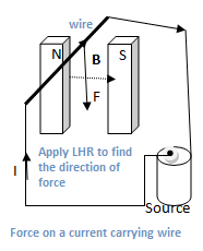
See the figure. A current-carrying wire is placed inside the poles of a magnet. When current passes through the wire, a force is experienced by the wire. It is observed that the direction of the force is perpendicular to both the direction of the magnetic field and the direction of the current in the wire.
Direction
The direction of the force on the wire can be determined by the Fleming’s Left Hand Rule which is stated as;
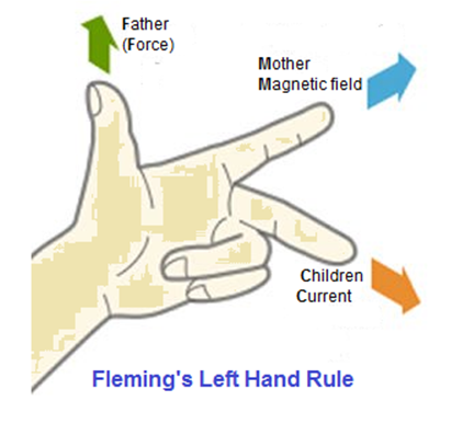
Fleming’s Left Hand Rule
The thumb, index finger and middle finger are set at right angles to one another like x, y and z-directions of coordinate axes. Set the index finger in the direction of magnetic field, middle finger in the direction of current, the thumb will point in the direction of force.
Magnitude calculation
It has been found after a number of experiments that if F is the force on the wire then;
(a) F is directly proportional to the amount of current flowing in the wire; F∝ I.
(b) F is directly proportional to the length L of the wire in the magnetic field; F ∝ L.
(c) F is directly proportional to the strength of the magnetic field B;
F ∝ B.
Combining all, F ∝ ILB
In SI units, the constant of proportionality is 1. Hence, F = IBL
If the wire is placed in the field B at some angle θ with it, then the force is given be

Here L is a vector whose magnitude is equal to the length of wire and direction is that of the current. Similarly, n̂ is unit vector in the direction of force and perpendicular to both L and B.
This also indicates that the magnetic force will be maximum when the current carrying conductor is placed perpendicular to the magnetic field, i-e, θ = 90o. Similarly, the force will be zero (minimum) when the current carrying wire is placed parallel to B, i-e, θ = 0o.
Explanation of B
Magnetic induction B is a vector quantity, therefore, having both direction and magnitude.
Direction of B
The direction of B at any point of the magnetic field is the direction in which the force acting on a straight current carrying wire, placed at that point is, zero.
Magnitude of B
When the angle between L and B is = 900 force F on the wire is maximum.

So it is the maximum force acting on a conductor having a length of 1 m, when one ampere current is flowing through a conductor.
Unit of B
The SI unit of magnetic field is B is tesla, denoted by T. From the above equation it is clear that 1 T = 1 N A-1 m-1.
Tesla is defined as “magnetic field at any point is said to be 1 tesla if it exerts a force of 1N on one meter length of the conductor placed there at right angle to the field when a current 1 A passes through the conductor.”
An older name for Tesla is “Weber per meter squared”, that is, 1 Wb.m-2 = 1T
Another commonly used unit in CGS is gauss (G).
1 G = 10-4 T
The magnetic field of earth is ½ G = ½ x 10-4 T.
Pingback:torque-on-a-loop-in-magnetic field … msa – msa
Pingback:Electromagnetism, Physics 12 … msa – msa